Ви не увійшли.
- Теми: Активні | Без відповіді
#1 2015-12-27 20:28:42
- ingenico
- Учасник

- З Киев
- Зареєстрований: 2015-12-27
- Повідомлень: 18
Продам GSM модули, LCD дисплеи, термопринтеры
Здравствуйте, участники форума!
Я здесь новичек, но что такое Arduino - я знаю.
Хочу предложить комплектующие из POS терминалов, которые я думаю можно подружить с Arduino.
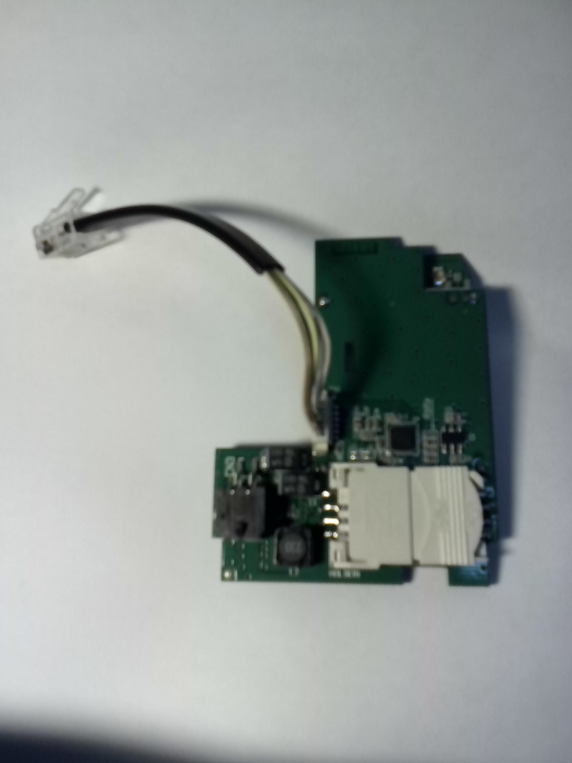
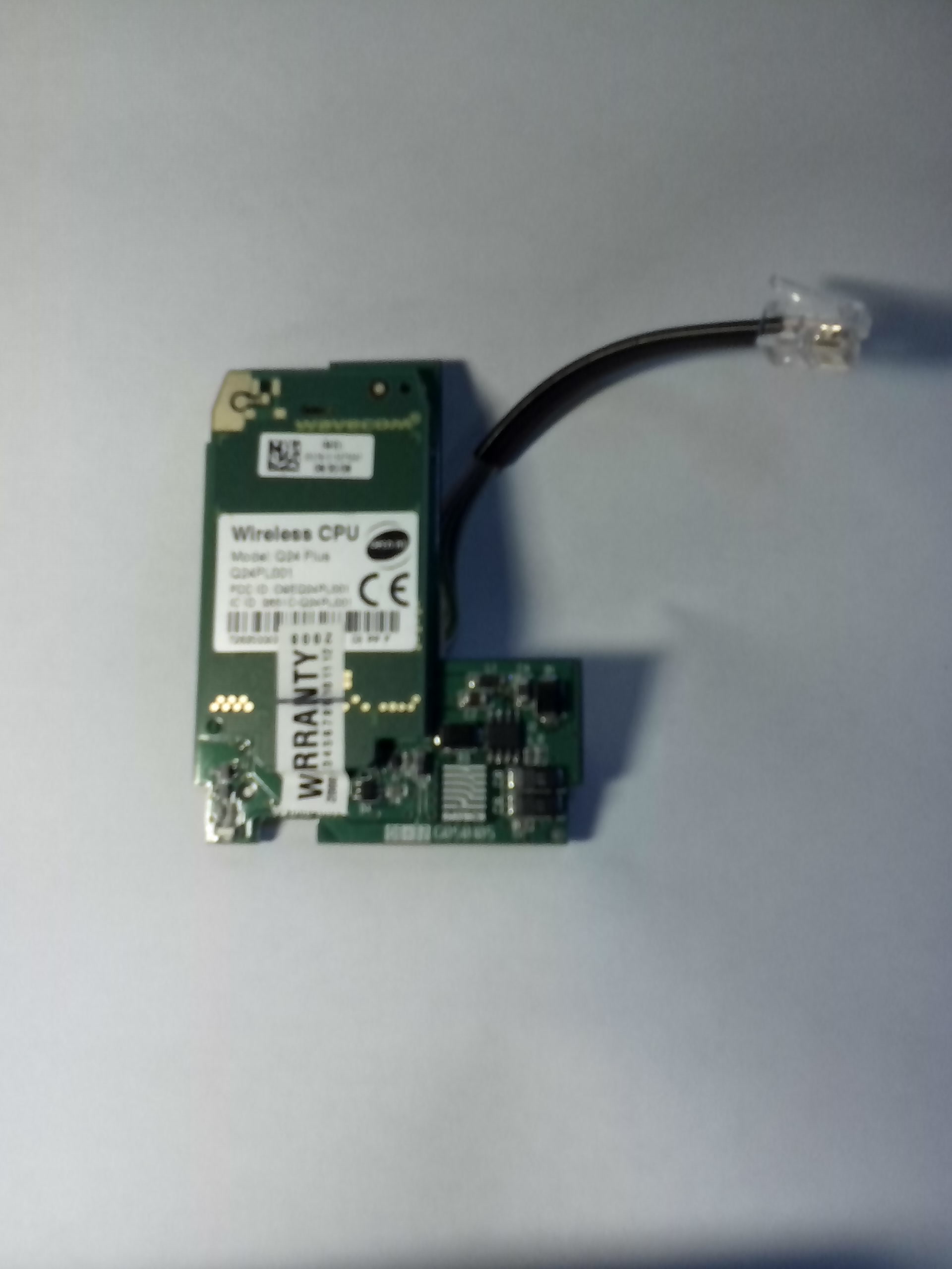
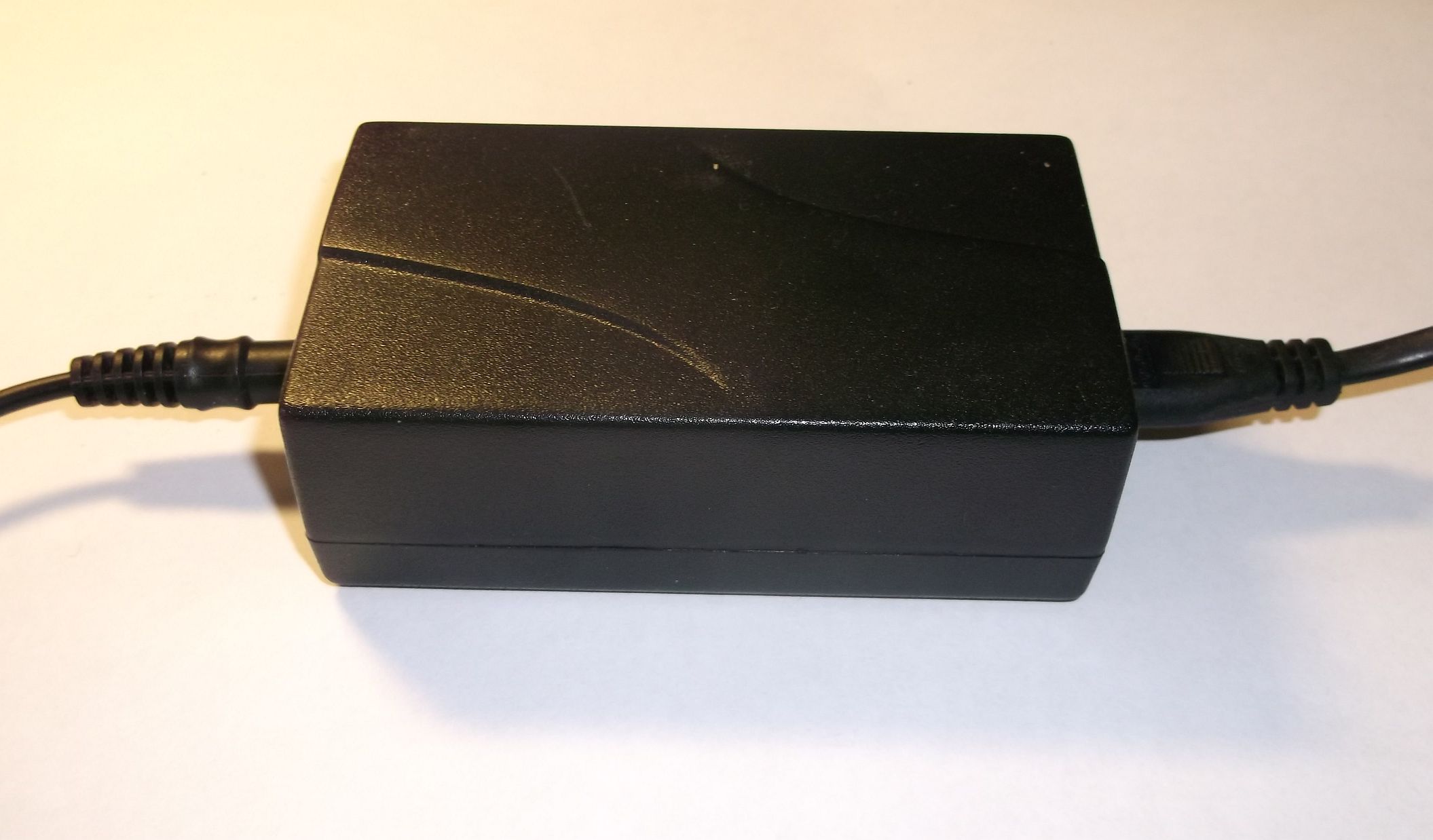
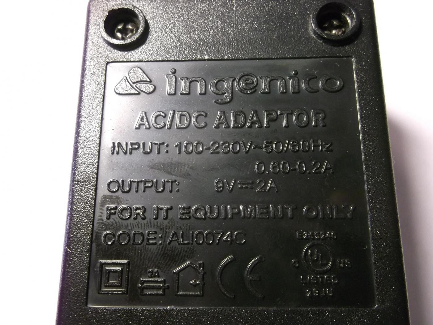
1. GSM модули, GPRS class 10, питание 9V, могу отдать с блоком питания.
2. LCD дисплеи 128х64.
3. Термопринтеры.
Терминалы такие:
hypercom t2100
ingenico 5100
ingenico 790 elite
вот тут показана разборка hypercom T2100
можно посмотреть маркировку lcd дисплея.
фото gprs модуля из ingenico 5100 оправлю завтра. документацию на него не нашел.
интерфейсный разъем RJ-11 , 6 контактов.
Кто из участников форума захочет разобратся и предоставить информацию - бесплатно дам 5 шт.
Ну собственно пока все. Жду предложений.
Неактивний
#2 2015-12-27 22:24:46
- Гoсть
- Гість

Re: Продам GSM модули, LCD дисплеи, термопринтеры
Цены бы озвучили хоть приблизительные
#3 2015-12-27 22:38:33
- ingenico
- Учасник

- З Киев
- Зареєстрований: 2015-12-27
- Повідомлень: 18
Re: Продам GSM модули, LCD дисплеи, термопринтеры
gsm модуль с блоком питания 9V и коннекторами питания на модуль и arduino 200 грн.
НО!
требуется тестирование работы модуля с arduino.
Поэтому я обращаюсь с участникам форума протестировать GSM-модуль выложить здесь результаты и оставить модуль себе ![]()
Неактивний
#6 2015-12-28 13:26:17
- NoName
- Customer

- З Київ
- Зареєстрований: 2014-07-08
- Повідомлень: 1,446
Re: Продам GSM модули, LCD дисплеи, термопринтеры
модем неплох
http://read.pudn.com/downloads137/ebook … deline.pdf
хорошие характеристики по потреблению в режиме сна,
и вообще вейвком хорош, берите
если не запустите - маякните.
а меня интересует принтер ) такого у меня никогда не было )
Неактивний
#8 2016-01-02 14:06:10
- ingenico
- Учасник

- З Киев
- Зареєстрований: 2015-12-27
- Повідомлень: 18
Re: Продам GSM модули, LCD дисплеи, термопринтеры
Термопринтеры:
http://www.konkurel.ru/fujitsu/tp/pdftp … 101_50.pdf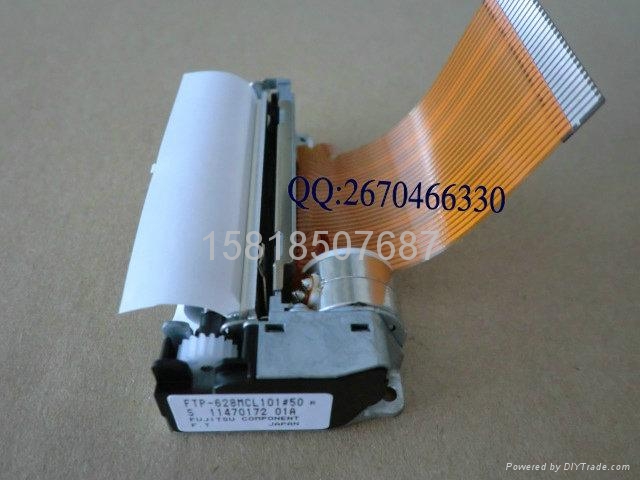
Неактивний
#9 2016-01-03 18:54:10
- ingenico
- Учасник

- З Киев
- Зареєстрований: 2015-12-27
- Повідомлень: 18
Re: Продам GSM модули, LCD дисплеи, термопринтеры
С помощью поддержки в модеме Open AT
можно настроить tcp клиента прямо в модеме,
или организовать соединение точка-точка по CSD.
Пример - снятие показаний электросчетчика с RS232 портом (Энергомера например)
модем неплох
http://read.pudn.com/downloads137/ebook … deline.pdf
хорошие характеристики по потреблению в режиме сна,
и вообще вейвком хорош, берите
если не запустите - маякните.а меня интересует принтер ) такого у меня никогда не было )
Неактивний
#12 2016-01-06 13:25:58
- NoName
- Customer

- З Київ
- Зареєстрований: 2014-07-08
- Повідомлень: 1,446
Re: Продам GSM модули, LCD дисплеи, термопринтеры
урл на все доступные фотки
https://www.dropbox.com/sh/13y94kp8c6an … kvbYa?dl=0
нужно переделать на более корректный свет и линейку что ли добавить для понимания габаритов, исправлюсь )
начнем с индикатора, PE12864-004
индикатор не заказной, это плюс
https://www.dropbox.com/s/vpbv508n2v3xz … S.jpg?dl=0
https://www.dropbox.com/s/bnmlvr9ealxc3 … 4.jpg?dl=0
подходящая документация -
https://www.dropbox.com/s/x5n66n0gp5e0p … H.pdf?dl=0
плюсы:
готовый конструктив, включающий в себя плату с установленными элементами для корректного запуска индикатора
подсветка дисплея ( должна быть %) , не проверил )
доступны крепежные элементы - "это важно )"
по умолчанию на плате шлейш, но доступна подпайка проводов
контраст приемлемый для такого типа индикаторов,
стандартный шрифт 8 на 5 - хорошо читаемый
Неактивний
#13 2016-01-13 01:24:57
- NoName
- Customer

- З Київ
- Зареєстрований: 2014-07-08
- Повідомлень: 1,446
Re: Продам GSM модули, LCD дисплеи, термопринтеры
PE12864 interface
1 	VSS Ground.These pads must be connected each other
2	VDD	2.4 - 3.5V power supply input.These pads must be connectedeach other.
3	V0	 NC
4	/RES	When RES is set to “L”, the settings are initialized. The operation is performed by the RES signal level .
5	/CS	This is the chip select signal. When CS1=“L” and CS2=“H”,
	then the chip select becomes active, and data/command I/O is enabled.
6	RS	 This is connected to the least significant bit of the normal MPU address bus, and it determines whether the data bits are data or a command.
A0 = “H”: Indicate that D0 to D7 are display data. A0 = “L”: Indicates that D0 to D7 are control data
7	/WR	When connected to an 8080 MPU, this is active LOW. This terminal connects to the 8080 MPU WR signal.The signals on the data bus are latched at the rising edge of the WRsignal. When connected to a 6800 Series MPU, this is the read/write control signal input terminal. When W R/ = “H”: Read, When W R/ = “L”: Write
8	/RD	When connected to an 8080 MPU, it is active LOW. This pad is connected to the RD signal of the 8080MPU, and the NT7532 data bus is in an output status when this signal is “L”.When connected to a 6800 Series MPU, this is active HIGH.This is used as an enable clock input of the 6800 series MPU
9~16	  D0~D7	This is an 8-bit bi-directional data bus that connects to an 8 or16-bit standard MPU data bus. When the serial interface is selected(P/S=“L”),Then serves as the serial data input terminal (SI) and D6 serves the serial clock input terminal (SCL). At this time, D0 to D5 are set to high impedance. When the chip select is inactive, D0 to D7 are set to high impedance.
17	A	Backlight input of positive
18	K	Backlight input of cathode
Неактивний
#14 2016-01-13 01:58:13
- Konstantin
- Гість

Re: Продам GSM модули, LCD дисплеи, термопринтеры
NoName IMHO достаточно просто указать, что драйвер ST7565S
#15 2016-01-13 02:10:09
- Konstantin
- Гість

Re: Продам GSM модули, LCD дисплеи, термопринтеры
#16 2016-01-13 10:43:02
- NoName
- Customer

- З Київ
- Зареєстрований: 2014-07-08
- Повідомлень: 1,446
Re: Продам GSM модули, LCD дисплеи, термопринтеры
Konstantin привет, не согласен, 72 страницы полезного английского текста ) но в нем отсутствует pin interface реальной железяки,
когда буду подключать - распиновку посмотрю на первой странице форума )
но за урл на драйвер - спасибо ) когда не запустится индикатор - обязательно почитаю )
так как форум читают новички, то по факту я отображаю последовательность действий. при поиске и обработке информации по незнакомой железяке, блог имени индикатора )
Неактивний
#17 2016-01-14 23:13:24
- Konstantin
- Гість

Re: Продам GSM модули, LCD дисплеи, термопринтеры
Приехали и мне пару терминалов и модем.
По мере разбирательства буду также писать сюда.
Применять клавиатуру и дисплей ИМХО разумно будет в составе имеющегося конструктива, а принтер ТОЛЬКО в составе терминала. Отдельно принтер применить практически не реально. Поэтому имеет смысл рассмотреть состав мат. платы терминала. К сожалению, простотой она не блещет.
Итак:
#18 2016-01-14 23:36:11
- Konstantin
- Гість

Re: Продам GSM модули, LCD дисплеи, термопринтеры
Состав мат. платы
K4S641632K-UC60 - Samsung - 67,108,864 bits synchronous high data rate Dynamic RAM organized as 4 x 2,097,152 words by 8 bits, / 4 x 1,048,576 words
http://www.rockbox.org/wiki/pub/Main/Ir … aSheet.pdf
BS62LV4006TCP70 - BSI - Very Low Power CMOS SRAM 512K X 8 bit
http://pdf1.alldatasheet.com/datasheet- … TCP70.html
SST39VF3201 - 2M x16, respectively, CMOS Multi-Purpose Flash Plus (MPF+)
http://ww1.microchip.com/downloads/en/D … 25028A.pdf
S3C44BOX01 - Samsung - ARM 16/32-Bit CMOS RISC Microprocessor
http://pdf1.alldatasheet.com/datasheet- … 44B0X.html
ATMEGA16-16MU - похоже контроллер принтера
74HCT4066D - 2 шт.
#19 2016-01-15 00:54:08
- Konstantin
- Гість

Re: Продам GSM модули, LCD дисплеи, термопринтеры
Состав мат. платы ( продолжение )
SN74LVC32APWRG3 - 2 шт. OR Gate 4-Element 2-IN CMOS 14-Pin TSSOP
SN74LVC00APW - NAND Gate 4-Element 2-IN CMOS 14-Pin TSSOP
TA550CPFB - Asynchronous Communications Element With Autoflow
http://www.ti.com/lit/ds/symlink/tl16c550c.pdf
BA6845FS - Драйвер ШД принтера
http://pdf1.alldatasheet.com/datasheet- … 845FS.html
ICL3232 CVZ - 2 шт. - Intersil, RS-232 Transceiver, 2T/2R, +3V to 5.5V, 250kbps.
http://www.intersil.com/content/dam/Int … -41-43.pdf
21006541 - читалка магн. полоски, Triple Track Delta ASIC with Shift-out; 3V - MagTek
https://www.magtek.com/docs/99875337.pdf
ATMEL 89C51IC2 - ATMEL x51 µP
http://www.atmel.com/images/doc4301.pdf
ICL7665 - Intersil, µP Voltage Monitor with Dual Over/Undervoltage
https://datasheets.maximintegrated.com/ … CL7665.pdf
MSP430F1121A - Texas Instruments, 16-bit Ultra-Low-Power µP, 4kB Flash, 256B RAM, Comparator
http://www.ti.com/product/MSP430F1121A
8007B_C3 - PHILIPS, TDA8007BHL Multiprotocol IC card interface
http://www.nxp.com/documents/data_sheet/TDA8007BHL.pdf
Еще пара мелких м-схем спряталась под батарейкой - но это уже завтра. ![]()
#20 2016-01-16 02:05:12
- Konstantin
- Гість

Re: Продам GSM модули, LCD дисплеи, термопринтеры
Состав мат. платы ( окончание )
Под батарейкой прятались:
SN74HCT32DBR - Texas Instruments, OR Gate 4-Element 2-IN CMOS 14-Pin SSOP
http://www.ti.com/lit/ds/symlink/sn74hct32.pdf
и
TI71AFL - MSOP8 - не нашел пока
ПИТАНИЕ - ВСЕ стабилизаторы - линейные:
1117M3 - 2 шт. SPX1117M3 - EXAR - 8800mA Low Dropout Regulator
https://www.exar.com/common/content/doc … shx?id=694
Один 3,3 вольта, другой 2,5 вольта.
LP8340CDT-5.0 - Texas Instruments, low-dropout CMOS linear regulator = 5V,
AT120A - BAT120, NXP - Schottky barrier double diodes
http://www.nxp.com/documents/data_sheet … SERIES.pdf
#21 2016-01-16 16:36:23
- Konstantin
- Гість

Re: Продам GSM модули, LCD дисплеи, термопринтеры
Состав дочерней платки
EPM3064A - ALTERA, MAX 3000A Programmable Logic Device Family
https://www.altera.com/en_US/pdfs/liter … m3000a.pdf
74LVC08A - 2 шт. Quad 2-input AND gate
http://www.nxp.com/documents/data_sheet/74LVC08A.pdf
TL5001 - Texas Instruments, Buck/Boost, Inverting Controller (External Switch)
http://www.ti.com/lit/ds/symlink/tl5001.pdf
FDC658P - Fairchild, Single P-Channel, Logic Level, MOSFET
https://www.fairchildsemi.com/datasheets/FD/FDC658P.pdf
===================================================
BQ2050 - Texas Instruments, Lithium Ion Power Gauge
http://www.ti.com/lit/ds/symlink/bq2050.pdf
BQ24006 - Texas Instruments, Linear 2-cell Li-Ion Battery Charger w/Integrated FET, Bi-Color LED
http://www.ti.com/lit/ds/symlink/bq24006.pdf
FDS4935 - - Fairchild, Dual 30V P-Channel PowerTrench® MOSFET –7 A, –30 V.
http://media.digikey.com/pdf/Data%20She … DS4935.pdf
Si4944DY - Vishau, Dual N-Channel 30-V (D-S) MOSFET
http://www.vishay.com/docs/72512/72512.pdf
#22 2016-01-16 16:47:23
- Konstantin
- Гість

Re: Продам GSM модули, LCD дисплеи, термопринтеры
Состав дочерней платки ( окончание )
LP339 - NXP, Ultra-Low Power Quad Comparator
http://www.ti.com/lit/ds/symlink/lp339-n.pdf
MBRB1045- 3 шт. SWITCHMODE Schottky Power Rectifier
http://www.onsemi.com/pub_link/Collater … 1045-D.PDF
MIC5015YM - 2 шт. Micrel Gate Drivers Low Cost Low/ High Side MOSFET Predriver, Inverting.
http://www.micrel.com/_PDF/mic5014.pdf
MPRV S14B - MSOP8 - пока не нашел что это.
Состав разобран, дальше рисовать схему или какие то ее куски.
#23 2016-01-19 00:57:29
- NoName
- Customer

- З Київ
- Зареєстрований: 2014-07-08
- Повідомлень: 1,446
Re: Продам GSM модули, LCD дисплеи, термопринтеры
набросок драйвера PE12864LRF-004-H на stm32l-discovery
мультики наверное имеет смысл сделать на raspberry и не в parallel mode
/**
  * @file    stm32l_12864_lcd.c
  * @author  NoName, Ukraine, Kiev, www.arduino-ua.com
  * @version V1.0.0
  * @date    2016.01.17
  * @brief   This file includes driver for the LCD Module PE12864 / driver ST7565S
	*          for check device
  * source http://edeca.net/wp/electronics/the-st7565-display-controller/
  * https://github.com/lxdengineering/demo_common/blob/master/st7565.h
  * http://www.winstar.com.tw/UserFiles/File/ST7565S-V06c-090907.pdf
*/

/* Includes ------------------------------------------------------------------*/
#include "stm32l_discovery_lcd.h"
#include "discover_board.h"
#include "main.h"

#define cDISPLAY_OFF      0xAE
#define cDISPLAY_ON       0xAF
#define cDISP_START_LINE  0x40  /* Set start line, 0..63    */
#define cPAGE             0xB0  /* Set page, 0..8           */
#define cCOL_MS           0x10  /* Set col, MS nybble       */
#define cCOL_LS           0x00  /* Sel col, LS nybble       */
#define cADC_NORMAL       0xA0
#define cADC_REVERSE      0xA1  /* Reverse segment order    */
#define cDISP_NORMAL      0xA6
#define cDISP_REVERSE     0xA7  /* Reverse lit/unlit pixels */
#define cALLPTS_NORMAL    0xA4
#define cALLPTS_ON        0xA5  /* All pixels on            */
#define cBIAS_9           0xA2  /* Voltage bias ratio, 1/9  */
#define cBIAS_7           0xA3  /* Voltage bias ratio, 1/7  */
#define cRMW_BEGIN        0xE0  /* Enter Read/Modify/Write mode */
#define cRMW_END          0xEE  /* Exit  Read/Modify/Write mode */
#define cRESET            0xE2  /* Reset most things (disp RAM not affected)*/
#define cCOM_NORMAL       0xC0
#define cCOM_REVERSE      0xC8  /* Reverse Com scan direction               */
#define cPOWER_CONTROL    0x28  /* D2:Booster; D1:Vreg; D0:Vfollower        */
#define cRESISTOR_RATIO   0x20  /* Set resistor ratio,          0..7        */
#define cVOLUME           0x81  /* 2-byte cmd: Set Vlcd (Vo). Next byte...  */
                                /*    volume-register 0..63                 */
#define cSLEEP_ENTER      0xAC  /* 2-byte cmd: Enter sleep mode (follow with 0) */
#define cSLEEP_EXIT       0xAD  /* 2-byte cmd: Exit sleep mode  (follow with 0) */

#define cBOOSTRATIO       0xF8  /* 2-byte cmd: Set V boost. Next byte...    */
                                /*    0: 2x,3x, or 4x                       */
                                /*    1: 5x                                 */
                                /*    2: 6x                                 */
#define cNOP              0xE3


// RAM LCD 128x64 (128*64)/8 = 1024
uint8_t GLCD[1024];

/*
1 	VSS Ground
2	VDD	2.4 - 3.5V
3	V0	 NC
4	/RES  PC0
5	/CS   PC1
6	 RS    PC2
7	/WR	  PC3
8	/RD	  PA0
9  	D0    PA1
10    D1    PA2
11	D2    PA3
12	D3    PA4
13	D4    PA5
14	D5    PB2
15    D6    PB10
16	D7	  PB11
17	A	Backlight input of positive
18	K	Backlight input of cathode
*/


#define pin_RES   GPIO_Pin_0
#define pin_CS    GPIO_Pin_1
#define pin_A0    GPIO_Pin_2
#define pin_WR	  GPIO_Pin_3

#define pin_RD	  GPIO_Pin_0
#define pin_D0    GPIO_Pin_1
#define pin_D1    GPIO_Pin_2
#define pin_D2    GPIO_Pin_3
#define pin_D3    GPIO_Pin_4
#define pin_D4    GPIO_Pin_5

#define pin_D5    GPIO_Pin_2
#define pin_D6    GPIO_Pin_10
#define pin_D7	  GPIO_Pin_11

#define port_RES   GPIOC
#define port_CS    GPIOC
#define port_A0    GPIOC
#define port_WR	   GPIOC

#define port_RD	   GPIOA
#define port_D0    GPIOA
#define port_D1    GPIOA
#define port_D2    GPIOA
#define port_D3    GPIOA
#define port_D4    GPIOA

#define port_D5    GPIOB
#define port_D6    GPIOB
#define port_D7	   GPIOB

#define allpin_portC (pin_RES|pin_CS|pin_A0|pin_WR)
#define allpin_portA (pin_RD|pin_D0|pin_D1|pin_D2|pin_D3|pin_D4)
#define allpin_portB (pin_D5|pin_D6|pin_D7)

void lcdWriteBuffer( uint8_t *buff);
void LCD_test_Clear( uint8_t data_clear_lcd );

// random, need recalculate
void pause_usec (uint32_t data )
{
int foo;
	while ( data > 0 )
	{
		for ( foo = 0 ; foo < 10; foo++ )
		{
	__NOP();
	__NOP();
	__NOP();
		}
		data--;
	}

}


void write_data_bus ( uint8_t data)
{
 if ( data & 0x01) GPIO_SetBits (port_D0,pin_D0); else GPIO_ResetBits (port_D0,pin_D0);
 if ( data & 0x02) GPIO_SetBits (port_D1,pin_D1); else GPIO_ResetBits (port_D1,pin_D1);
 if ( data & 0x04) GPIO_SetBits (port_D2,pin_D2); else GPIO_ResetBits (port_D2,pin_D2);
 if ( data & 0x08) GPIO_SetBits (port_D3,pin_D3); else GPIO_ResetBits (port_D3,pin_D3);
 if ( data & 0x10) GPIO_SetBits (port_D4,pin_D4); else GPIO_ResetBits (port_D4,pin_D4);
 if ( data & 0x20) GPIO_SetBits (port_D5,pin_D5); else GPIO_ResetBits (port_D5,pin_D5);
 if ( data & 0x40) GPIO_SetBits (port_D6,pin_D6); else GPIO_ResetBits (port_D6,pin_D6);
 if ( data & 0x80) GPIO_SetBits (port_D7,pin_D7); else GPIO_ResetBits (port_D7,pin_D7);
}
// no use
void write_lcd_full_command ( uint8_t cmd, uint8_t data )
{
	// cmd:0 - RS/A0
	// cmd:1 - RD
	// cmd:2 - WR
 if ( cmd & 0x01) GPIO_SetBits (port_A0,pin_A0); else GPIO_ResetBits (port_A0,pin_A0);
 if ( cmd & 0x02) GPIO_SetBits (port_RD,pin_RD); else GPIO_ResetBits (port_RD,pin_RD);
 if ( cmd & 0x04) GPIO_SetBits (port_WR,pin_WR); else GPIO_ResetBits (port_WR,pin_WR);
 write_data_bus	(data);

 GPIO_ResetBits (port_A0,pin_A0);
 GPIO_ResetBits (port_RD,pin_RD);
 GPIO_ResetBits (port_WR,pin_WR);

}

void write_lcd_command ( uint8_t data )
{

  GPIO_ResetBits (port_A0,pin_A0);
	GPIO_SetBits 	(port_RD,pin_RD);
  GPIO_ResetBits (port_CS,pin_CS);
	write_data_bus	(data);
	GPIO_ResetBits ( port_WR,pin_WR );
 	pause_usec (10);
  GPIO_SetBits 	 ( port_WR,pin_WR );
 	pause_usec (10);
  GPIO_SetBits (port_CS,pin_CS);
//----------
	GPIO_SetBits (port_A0,pin_A0);
	GPIO_SetBits 	(port_RD,pin_RD);

}


void write_lcd_data ( uint8_t data )
{
 write_data_bus	(data);
 GPIO_ResetBits ( port_WR,pin_WR );
 pause_usec (10);
 GPIO_SetBits 	 ( port_WR,pin_WR );
 pause_usec (10);
}

void LCD_Configure_GPIO(void)
{

  GPIO_InitTypeDef GPIO_InitStructure;

/* Enable GPIOs clock */
  RCC_AHBPeriphClockCmd(RCC_AHBPeriph_GPIOA | RCC_AHBPeriph_GPIOB | RCC_AHBPeriph_GPIOC |
                        RCC_AHBPeriph_GPIOD | RCC_AHBPeriph_GPIOE | RCC_AHBPeriph_GPIOH, ENABLE);

  GPIO_StructInit(&GPIO_InitStructure);
  GPIO_InitStructure.GPIO_Pin = allpin_portC;
  GPIO_InitStructure.GPIO_Mode = GPIO_Mode_OUT;
  GPIO_Init( GPIOC, &GPIO_InitStructure);

  GPIO_InitStructure.GPIO_Pin = allpin_portA;
  GPIO_InitStructure.GPIO_Mode = GPIO_Mode_OUT;
  GPIO_Init( GPIOA, &GPIO_InitStructure);

  GPIO_InitStructure.GPIO_Pin = allpin_portB;
  GPIO_InitStructure.GPIO_Mode = GPIO_Mode_OUT;
  GPIO_Init( GPIOB, &GPIO_InitStructure);

  GPIO_SetBits (GPIOB,allpin_portB);
  GPIO_SetBits (GPIOA,allpin_portA);
  GPIO_SetBits (GPIOC,allpin_portC);

}

void LCD_test_Clear( uint8_t data_clear_lcd )
{
  uint16_t foo;

	for (foo = 0; foo < 1024; foo++ )
  GLCD[foo] = data_clear_lcd;  // test

	lcdWriteBuffer(&GLCD[0]);
}

void LCD_GLASS_Init(void)
{
int resistorRatio = 2;
uint8_t test = 0;

 GPIO_ResetBits (port_RES,pin_RES);
 pause_usec(2000);
 GPIO_SetBits (port_RES,pin_RES);
 pause_usec(20000);

    write_lcd_command(cADC_NORMAL);            // Normal segment order
    write_lcd_command(cCOM_NORMAL);            // Normal common order
    write_lcd_command(cBIAS_9);                // Set 1/9 bias

    pause_usec(2);

    write_lcd_command(cBOOSTRATIO);            // Enter boost ratio set mode, and then...
    write_lcd_command(0);                      //   set boost ratio to 2x/3x/4x

    write_lcd_command(cPOWER_CONTROL | 4);     // Booster on.
    write_lcd_command(cPOWER_CONTROL | 6);     // Boost, regulator on.
    write_lcd_command(cPOWER_CONTROL | 7);     // Power boost, regulator, and follower all on

    // Contrast/Brightness settings
    // Limit to 0..7 or less
    write_lcd_command(cRESISTOR_RATIO | (0x05&0x07)); // resistor
    pause_usec(2);
    write_lcd_command(cVOLUME);                // Volume register set (LCD voltage, Vo). Next byte is...
    write_lcd_command((60) & 0x3F);          //    the "volume", 0..63 (0x00..0x3f).
   write_lcd_command(cDISPLAY_ON);            // Turn display on
 // test
 while(1)
 {
   LCD_test_Clear(test++);
 }
}


uint8_t lcdDataArray(const uint8_t data[], int n)
{
    int i;

 GPIO_SetBits 	( port_A0,pin_A0 );
 GPIO_SetBits 	( port_RD,pin_RD );
 GPIO_SetBits 	( port_WR,pin_WR );
 GPIO_ResetBits ( port_CS,pin_CS );

    for(i=0; i<n; i++)
    {
		 write_lcd_data (data[i]);
    }

 GPIO_SetBits (port_CS,pin_CS);
   return 0;
}

void lcdWriteBuffer( uint8_t *buff)
{
 	uint8_t page;

    for(page = 0; page < 8; page++)
    {
        write_lcd_command(cPAGE | (page));
        write_lcd_command(cCOL_MS );
        write_lcd_command(cCOL_LS );
        lcdDataArray(buff, 128);
        buff += 128;
    }
	}
Konstantin , Ваш обзор впечатляет, просто нет слов )
под микроскопом маркировку смотрели?
в вашем комплекте такая плата есть?
https://www.dropbox.com/s/7gz6aare9oue9 … 9.jpg?dl=0
S14B - как вариант
http://pdf.datasheetcatalog.com/datashe … lm3478.pdf
Остання редакція NoName (2016-01-19 01:21:47)
Неактивний
#24 2016-01-19 02:43:19
- Konstantin
- Гість

Re: Продам GSM модули, LCD дисплеи, термопринтеры
NoName, смотрел глазами, а местами лупой. ![]()
Такая плата у меня есть, ничего интересного - обычный проводной Conexant-овский модем.
Типа такого: http://www.conexant.com/wp-content/uplo … X81801.pdf
S14B - похоже, вы определили правильно. Нужно будет сверить со схемой.
Если возможно, дублируйте ваши кодовые вставки в виде файла - очень неудобно читать в окне.
#25 2016-01-19 03:32:18
- Konstantin
- Гість

Re: Продам GSM модули, LCD дисплеи, термопринтеры
TI71 AFL - MSOP8 - BACKUP-BATTERY SUPERVISORS FOR RAM RETENTION
http://www.ti.com/lit/ds/symlink/tps3620-33-ep.pdf
==========================================================
Немного по GSM модему:
Большой архив с документацией (в т.ч. SDK):
http://archive.sierrawireless.com/Defau … l_devices\
На плате:
TPS5430 - Texas Instruments, 5.5V to 36V Input, 3A, 500kHz Step-Down Converter
http://www.ti.com/lit/ds/symlink/tps5430.pdf
ADM3307 - Analog Devices, +2.7V Serial Port RS-232 Transceiver (5 Drivers / 3 Receivers)
http://www.analog.com/media/en/technica … _3315E.pdf
Z8 - SOT23-6 - Защитная диодная сборка для SIM-карты ???
28E J18 - SOT89-6 - XC6202PD52PR - Torex Semiconductor - Linear voltage regulator integrated circuit
http://www.torexsemi.com/products/volta … XC6202.pdf
